Skip to content

{ Category Archives } PCB

TimVideos.us 2016 New Year’s Resolutions

This is a cross post from the HDMI2USB website about my plans for 2016 and the TimVideos project. Last year was an exciting time for my personal projects!

TimVideos.us 2016 New Year’s Resolutions


Hello everyone,

Hope everyone has had an awesome start to 2016 so far. As is tradition in many western countries, I thought I would put together some New Year’s Resolutions and reflect on our progress in 2015. I guess more business minded people might call it a “project roadmap” 🙂

TimVideos Project

In 2015, I decided to focus the TimVideos project on the HDMI2USB project. The three key results of this focus were;

With the success of this focus in 2015, the TimVideos project is going to continue to focus on theHDMI2USB project for 2016 (and I’ll go into more detailed goals shortly).

The TimVideos project has also been mildly successful in collaborating with other open source groups doing things related to video recording and production. In 2016, I hope we can strengthen these bonds and forge new ones. Some specific goals around this include;

HDMI2USB Project

As we are concentrating on the HDMI2USB project, we have some specific goals around that.

HDMI2USB firmware goals;

  • Refactor the HDMI core to allow support a wider range of interfaces, better debugging and addition of more features. A document about the refactor has been started here.
  • Add support for the high-speed GTP transceivers and Mike “Hamster” Field open source DisplayPort core.
  • Get Ethernet support working (on both the Atlys and Opsis boards). The two major Ethernet features are;
    • Ethernet supports identical capture and control feature set to the USB port.
    • Allowing HDMI2USB boards to act has “HDMI over Ethernet extenders”.
  • Support for more hardware;
    • miniSpartan6+
    • Digilent Nexys Video
    • New HDMI2USB designed hardware!
  • Stretch Goals (1)

HDMI2USB hardware goals;

  • (By end of year) Development of a low cost PCI-Express capture card.
  • (By middle 2017) Development of an Opsis V2 based around either an high end Artix-7 or a low end Kintex-7 FPGA.

(1): Stretch goals are things we plan to try and achieve if things go well.

Hope this update give you an idea of what we have planned for 2016! We would love your help making it all possible.

Tim ‘mithro’ Ansell

CFXS free at last!

Those who either know me personally, or have read more of my blog might remember my final year honours project. The project was to build a budget 8 line USB channel bank. Originally, I had hope to commercialise the project, the prospects looks good until two competing products where released into the market for only a slightly higher cost point. I had always hoped to make the system a piece of open hardware, but both the Uni rules and trying to commercialise it had made that difficult.

As a strange coincidence, David Rowe, a guy doing open source embedded Asterisk hardware, lives less then 15 minutes walk from my home. His main motivation behind this open hardware is to try and bring technology to the developing world in a way which empowers them instead of making them dependent on external supplies. We got chatting at a local LinuxSA meeting and he was partly inspired by my device to start the $10 ATA project. (David also has a bunch of other cool projects like his own electric car and trying to go off the grid).

Sometime during that, I removed the access controls on the subversion repository that I had used for the CFXS so that David could look at it. It turns out though, that I never told anyone else! So that is the main aim of this post, to tell you all where you can get a copy of source files for my honours project.

The subversion repository is located at the following url http://verbal.mithis.com/svn/cfxs/trunk/. You can check it out using the following subversion command,

svn co http://verbal.mithis.com/svn/cfxs/trunk cfxs

So why not check it out and build your own? I have some left over components which I’m happy to dole out if you agree to actually use them in a useful way. Just send me an email.

David (hopefully I’m not putting words in his mouth here) is hoping that we can use this device in combination with the OLPC XO laptop to bring telephony to a whole village. The mesh networking wireless would be ideal for doing VOIP, while my 8 port CFXS device and some very cheap handsets can give a bunch of people “real” phones. The system can also be made very low power as both the OLPC and the CFXS device can be in power down modes while nothing is happening.

So I guess we will see what happens in the near future, it seems like it’s an exciting area of FOSS to be involved in. Sadly, I don’t have much time to work on any of this.

Almost there..

Well, I’ve almost finished my Honours project, less then a week left until it’s done. I have been working on this project officially for almost a year now, however it’s original inception occurred about 2 and a half years ago.

For those who don’t know, my project is to build a budget 8 line computer to telephone interface. My hope was to eventually be able to sell the device for $US 150, allowing somebody to interface a whole house cheaply. The design is nothing more then a glorified ADC/DAC device – the computer its connected to does all the work.

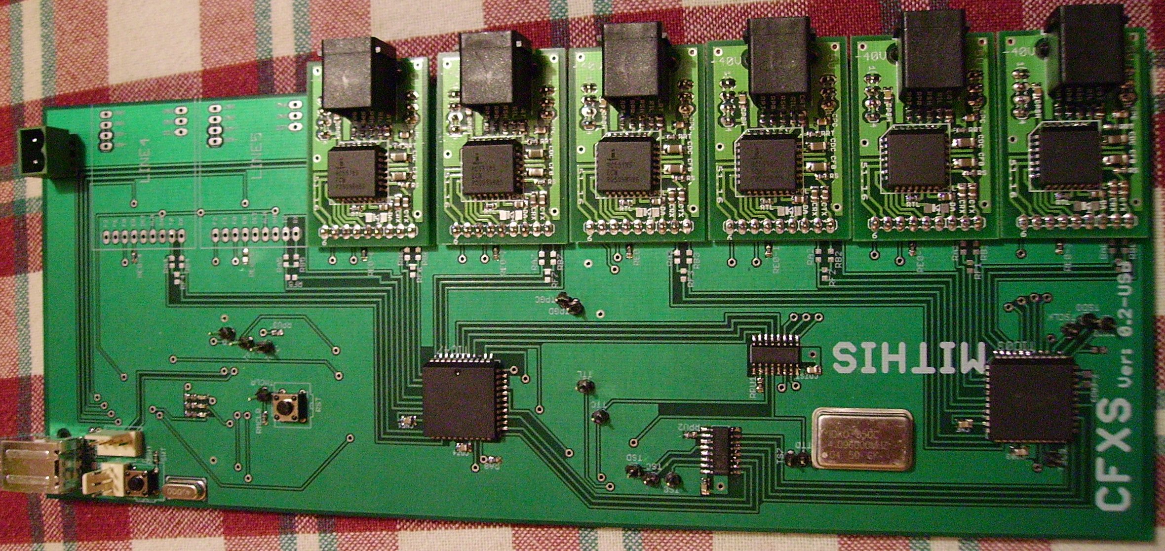
I have built a prototype board which is working a lot better then expected, you can see it below. I will however be glad when I can get back to just working on the board instead of writing all this documentation. Anyway, I should get back to it.

CFXS Try2 PCB Board

eagle2geda Symbol Converter

Well, after the last post I thought I would give the Eagle to gEDA converter a try. At first I thought about reverse engineering the Eagle format and then output the result. This would have the advantage that you wouldn’t need to run Eagle to do this. I decided that this would be too much work and was about to give up, but then I remembered that Eagle has quite a good scripting language called ULP. About 2 hours later I have this script which converts “symbols” in an Eagle library to a gEDA symbol. As this seems so easy I may continue and see if I can make a converter for a complete Schematic and PCB. I’ve attached a picture of a symbol in both gschem and Eagle at the same time.Hope other people find this useful too. Component in Eagle and gschem

Eagle for PCB

PCB Board for my Honors Project

For the last 3 days I have been working on routing the Honours project. For the design I use CadSoft Eagle. However, it’s been annoying me quite a bit.Here is just a shortlist of things,

  • You can’t change pads unless you modify a library. At my Uni they use a rivet system for doing plated through holes, these means that the holes and pads have to be a certain size as you have to solder the rivets to the pads. This means that you often want to change a hole and pad for a particular instance of an IC so that it can have a rivet put in it.
  • Polygon Pours can not be put in “outline” mode. This makes it quite annoying, as you want to put in the GND plane first so it removes all the GND airwires, but then you are constantly using the “rip-up” command so you can see where you are putting signals.

I’m thinking of moving to gEDA because it’s free software, I would no longer be restricted with what I do. However, it’s quite hard to use and doesn’t come with the extensive libraries that Eagle has.

I’m thinking that I’m going to write a ULP script which converts EAGLE stuff to the format used by gEDA. We’ll see what happens.